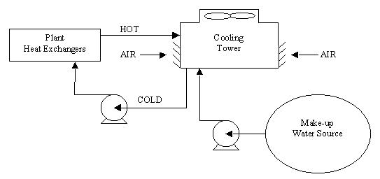
Cooling Tower Calculations software program is a powerful, user friendly, software program for the analysis of induced, mechanical-draft, counterflow cooling towers. The software program can be used for the analysis of existing towers or for the preparation of specifications for new towers.


• the value of NTUm for design conditions is calculated; • the line of slope n and constant C is plotted and adjusted on the design point; • for other operating conditions, determined by the fluid flows, the abacus allows us to find, at abscissa L/G and on the tower characteristic line, the new values of NTUm and approach, which determines the outlet water temperature and therefore the capacity. Driver camera axioo pico software tutorial4525507 windows 10. Download driver modem speedup untuk windows 8. The air outlet temperature is deduced. For another cooling or other air wet bulb temperature, it is possible to recalculate another abacus. Knowing the values of variables (NTUm, L/G) from the original chart, we get the new approach.
It seems necessary to warn the reader: we tried to implement this approach on some experimental data either provided by the manufacturers or that we were able to get, and we realized that, when applied to NTUm, the correlations of the type Merkel lead to accurate reconstructions with values n and m close to those we have indicated. However they may be different when we use an (epsilon, NTU) approach similar to those of dry heat exchangers. We recommend extreme caution when using this analogy, and think it is better to apply the Merkel model which has been proven and is used by the profession. The calculations are slightly more complex, and can be made with small programs or Excel macros.
The cooling tower itself should be modeled as a tank with design data entered through the Tank property grid as shown in Figure 3. • Elevation should be set to the elevation of the bottom of the basin of the cooling tower. • Surface Pressure should be set to 0.0 psig if the cooling tower is open to atmosphere.
If the cooling tower is pressurized or under vacuum, the pressure (or vacuum) exerted on the surface of the liquid should be entered. • Liquid Level should be set to the level of the liquid as measured from the bottom of the tank, typically the basin depth (5 feet in the model shown above) for cooling towers. Click the Penetrations field of the Tank's property grid to open the Tank Penetrations dialog box, shown in Figure 4. This is where you must specify the Penetration Height of each pipe connected to the tank.
For example, the return sprayers come in to the top of the cooling tower at 20 feet measured from the bottom of the tower. The outlet pipe to the suction of the pump penetrates the tower at the bottom of the tank, or 0 feet. The default penetration height is 0 feet (or meters if metric units are selected). Figure 4. Tank Penetrations dialog box to define the height at which each pipe enters the tank, as measured from the Bottom Elevation of the tank.